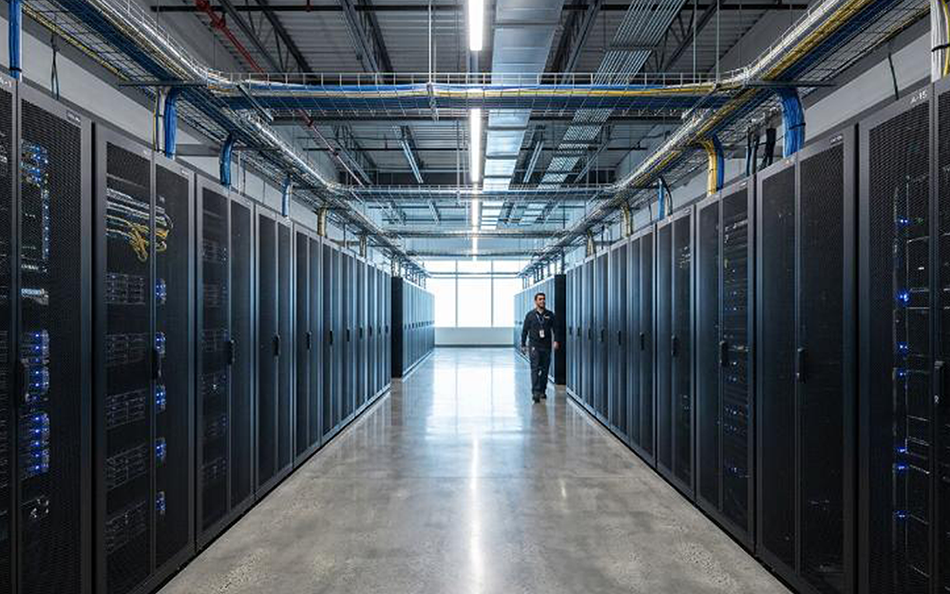
How Belimo Secondary Fluid Network Works
19 October 2026
In the fast-paced era of Artificial Intelligence (AI), High-Performance Computing (HPC), and expanding cloud infrastructure, power densities per rack in data centers are climbing at unprecedented rates. Traditional air cooling methods are quickly reaching their physical limits and struggle to efficiently dissipate these high heat loads.
To solve this, the data center industry is rapidly adopting Liquid Cooling solutions. Within liquid cooling architectures, the operation of a Secondary Fluid Network plays a pivotal role in maintaining system stability—and intelligent field devices from Belimo sit right at the core of this operation.
What is a Secondary Fluid Network in a Data Center?
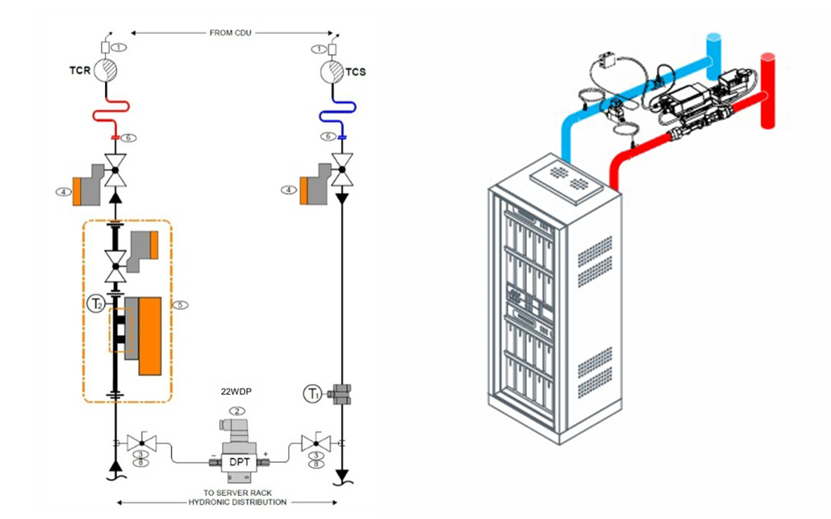
Modern data center liquid cooling systems typically split the hydronic design into two main loops separated by a heat exchanger unit known as a Cooling Distribution Unit (CDU):
- Primary Loop: Connects the primary facility equipment—such as central chillers, cooling towers, or dry coolers—to the supply side of the CDU. This loop circulates Facility Water System (FWS) fluid, which usually meets standard industrial water quality levels.
- Secondary Loop - Secondary Fluid Network (SFN): A dedicated, high-purity, and precisely temperature-controlled loop (often called the Technology Cooling System or TCS). It distributes conditioned fluid from the CDU directly to critical IT components inside the rack, such as CPU/GPU cold plates.
The Mode Operation of Belimo Devices in the Secondary Loop
The electronic differential pressure controller is used to maintain the differential pressure (dp) at a constant set value between two points in a hydronic circuit. In addition, it can be used as a flow rate and power limiter.
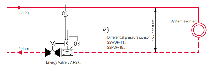
In this control mode, the Energy Valve does not receive a setpoint from the building management system. The differential pressure sensor connected with the Energy Valve measures the current differential pressure. This value is read out of the Energy Valve and compared with the preset setpoint. If a deviation is detected between the measured value and the setpoint, this is compensated automatically by the logic integrated in the Energy Valve. To accomplish this, the opening angle of the characterised control valve integrated in the Energy Valve is either enlarged or reduced. The following three operating states can occur:
- Effective differential pressure less than the differential pressure setpoint
To reduce the pressure drop across the Energy Valve and thus increase the differential pressure between the measuring points, the valve is opened further until the setpoint is reached. If the differential pressure on the system side is not sufficiently high, the setpoint may not be reached. In this case, the Energy Valve moves to the maximum opening position of 90°.
- Effective differential pressure corresponds to the differential pressure setpoint
No action of the Energy Valve. The opening position is retained.
- Effective differential pressure greater than the differential pressure setpoint
To reduce the differential pressure between the two measuring points, more pressure drop must be generated across the Energy Valve. In this case, the valve opening is reduced until the setpoint or minimum position is reached. The ball valve installed in the Energy Valve is never completely closed during standard differential pressure control mode in order to ensure that changes in the system (change in pump head or flow changes due to controlling consumer valves) can be detected.